Due to Saudi Arabia’s blistering heat, air conditioning is required to maintain comfort and proper building function. Newer construction projects have started to use VRF systems for their adaptable and efficient features, though many prefer to use alternative systems due to their steep learning curve. A VRF air conditioning system diagram uses technical language to describe the system and its components, providing an air conditioning VRF system explained in a clear and structured way to help achieve optimal and consistent design for the harsh climates of Saudi Arabia. Visit our page if you want to install vrf hvac system in ksa.
How to Read a VRF Air Conditioning System Diagram for Beginners
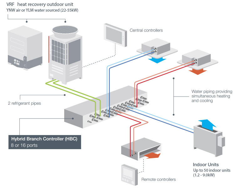
Identifying the Outdoor Unit
The first step in a VRF air conditioning system diagram is to locate the outdoor unit. This unit is usually shown at the starting point of the diagram. It is responsible for compressing the refrigerant and sending it into the system. Beginners should always start from here to understand the overall flow.
Following the Refrigerant Flow
After the outdoor unit, the diagram shows refrigerant moving through pipes. Beginners should trace these lines carefully, as they represent how cooling travels inside the system. This step helps in understanding how different areas receive cooling.
Recognizing Branch Controllers
In most VRF system diagrams, branch controllers are shown between the piping network and indoor units. These components divide and control refrigerant flow. Beginners should focus on how these are connected, as they explain how cooling is distributed to multiple rooms.
Understanding Indoor Units Placement
The diagram shows multiple indoor units connected to the system. Each unit represents a room or zone. Beginners should observe how each indoor unit is linked to the main system and how cooling is delivered separately.
Observing System Connections
A VRF air conditioning system diagram clearly shows how all components are connected. Beginners should look at the full layout to understand how the outdoor unit, piping, controllers, and indoor units work together as one system.
How to Analyze a VRF Air Conditioning System Diagram for Professionals
Analyzing System Layout and Design
In a VRF air conditioning system diagram, professionals first focus on the overall layout. The diagram shows how the outdoor unit is connected to multiple indoor units through a structured piping network. This helps in evaluating whether the design is suitable for the building size and cooling requirements. See full blog on VRF System Working Principle.
Evaluating Refrigerant Flow Control
Professionals use the VRF system diagram to understand how refrigerant is distributed across different zones. By analyzing flow paths and branch connections, they can ensure that each indoor unit receives the correct amount of refrigerant for efficient performance.
Planning Piping Routes and Connections
The diagram provides a clear view of piping routes, including main lines and branch connections. Professionals rely on this to plan accurate installation, avoid incorrect routing, and ensure proper connections between all components.
Assessing Zoning and Load Distribution
A VRF air conditioning system diagram helps professionals understand how cooling load is divided across different areas. By reviewing how indoor units are grouped, they can ensure balanced cooling and avoid overloading or underperformance in specific zones.
Verifying System Integration and Control
The diagram also shows how control systems are connected with indoor and outdoor units. Professionals use this information to ensure that temperature control, communication, and system coordination work correctly in real operating conditions.
Need Expert Help with VRF System Design in Saudi Arabia?
If you are starting a new project, or if you are having problems with your current HVAC system, we can help you assess and apply the best VRF solution. We support projects throughout Saudi Arabia, and you can count on us to help you with system design and installation.
Get Better Cooling Results with the Right VRF System Diagram in Saudi Arabia
An accurate VRF air conditioning system diagram guarantees optimal refrigerant distribution, proper system integration, and equitable cooling throughout all zones. In Saudi Arabia’s high temperatures, this positively impacts building performance, minimizes installation problems, and maximizes energy efficiency in residential and commercial buildings. At Airlution, we implement sophisticated VRF system design and focused diagram assessment to offer KSA effective energy HVAC solutions.
Conclusion
A VRF air conditioning system diagram provides a detailed overview of a VRF system and its components. This diagram helps both novices and experts in KSA circumvent expensive errors and ensures dependable and efficient cooling. At Airlution, we offer top-of-the-line VRF solutions with high performance and energy efficiency across Saudi Arabia. This is made possible thanks to the combined expert design and detailed diagram analysis. Contact us for help with VRF system design and HVAC solutions to meet the needs of your project.
FAQs:
What is a VRF air conditioning system diagram?
It shows how VRF systems connect and deliver efficient cooling across buildings.
Why do VRF system diagrams matter in Saudi Arabia?
They help prevent cooling issues, reduce costs, and improve HVAC performance in extreme heat.
How can I understand a VRF system diagram easily?
Follow refrigerant flow, identify units, and study system connections step by step.
What mistakes happen without a VRF system diagram?
Wrong installation, uneven cooling, and higher electricity bills are common issues.
How does a VRF diagram improve cooling efficiency?
It ensures proper system design, balanced cooling, and optimized energy usage.